Weighty Matters: An overview of in-situ load testing
by Katie Daniel | April 8, 2015 10:36 am
 [1]
[1]by Filippo Masetti, PE, Antonio De Luca, PhD, and Milan Vatovec, PE, PhD, LEED AP
In-situ load testing is a powerful tool to assess the performance of structures with respect to their ability to carry code-prescribed loads. The practice dates back to the late 1800s and has been used to verify the load rating of structures, as well as the expected performance of structures in retrofit, repair, and strengthening applications.
While not always considered the most cost-effective solution (often unjustly), these tests are especially powerful in situations where structures or components may be deemed inadequate to carry the intended loads and are slotted for potentially expensive retrofit or strengthening work. This is because other conventional and even sophisticated analysis methods may be unable to adequately assess reserve capacity due to the inherent inability to properly account for in-situ redundancy, load sharing, and effects of alternate load paths.
This article provides a historical review of the load-testing practice, a description of the state-of-the art protocols and methods for load testing (and their rationale), and a review of several related building codes and standards. It also provides a lessons-learned discussion based on real-life case study examples.
When can a load test be useful?
Load testing had been developed to either create a “confidence in the ability of a structure to perform” or “understand and define the mechanism of a specific structural behavior.” To this end, load test practices have been designed to determine whether the structure can safely support the proposed loading (i.e. building-code required loads), and are not aimed at providing an indication of the ultimate strength of the subject structure or its components, whose performance may be in question in a wide variety of situations.
Specifically, load tests can be used to evaluate structures exhibiting signs of deterioration and distress whose severity and extent is not fully understood. For instance, these authors worked on the evaluation of the concrete-bleachers structure of the concrete stadium of a prominent university in the Midwest. This investigation campaign included destructive sampling and non-destructive testing (e.g. impulse response, ground-penetrating radar) aimed at identifying extent of delaminated areas, followed by in-situ load testing of the worst-identified areas (which yielded sufficient load rating of the structure).
Similarly, load tests can evaluate the effects of design or construction defects, such as misplacement or omission of steel reinforcement within concrete elements, or use of lower-grade steel elements in construction. The authors were involved with a parking-garage project evaluating the negative-moment capacity of a flat slab in which the top reinforcing steel was misplaced (i.e. lower than specified in the construction documents). For this particular job, load testing was used to assess the performance of repair/strengthening details designed to address the slab’s reduced negative-moment capacity.
Moreover, load testing can be used to investigate performance of unique designs (i.e. proprietary systems) and/or historical/archaic structures where construction is not fully understood due to lack of documentation, concealed conditions, or inability to make exploratory openings. As an example, the authors worked on load testing of a late-1800s brick-masonry-arch floor systems in New York City.
Historical review of the load-testing practice
The practice of load testing has very deep roots, with
its development dating back to the 1870s in Europe.
A “very early example of proof load testing” was reported in New York in 1894. At that time, the concept was introduced to evaluate novelty and proprietary systems, which then largely consisted of reinforced concrete structures (such as the Turner system for flat slabs).
Although largely based on a rule-of-thumb approach, the first building-code reference to load-test protocol for reinforced-concrete structures appeared in the 1903 New York City Building Regulations. Five years later, a national code requirement for load testing for concrete structures was issued by the National Association of Cement Users (NACU), which became the American Concrete Institute (ACI).
The code was updated several times, but the general protocol remained conceptually unchanged:
- Threshold measurements of the structural parameters are taken before application of any load.
- The structure is loaded to a certain level, and structural parameters are recorded.
- Based on the measurements taken in the previous phases, the structure is evaluated.
Since the early days, as understanding of the relationship between the loads and reliability of structures increased, the load-test procedures in the ACI code also slowly changed. The main features that evolved over time can be summarized as:
- load test duration;
- establishment of test load magnitude (based on the design dead, live, and other loads required by the current code); and
- establishment of acceptance criteria to determine the outcome of the test (based on both maximum recorded deflections and recovery from maximum deflections).
Figure 1 summarizes the evolution of these features in the ACI load test provisions from 1920 to 2005.
 [2]
[2]
Load test protocols and acceptance criteria
Over the years, researchers and practitioners have investigated various methods for applying test loads and measuring structural-response parameters. To date, universally accepted (and very specific) load-test protocols are available for concrete structural systems.
Although less detailed, protocols for load testing steel buildings are also available. These protocols, published by ACI and the American Institute of Steel Construction (AISC), are currently adopted and enforced by International Building Code (IBC) and most of the local building codes.
ACI 318-14
The in-situ load test protocol adopted by ACI is outlined in Chapter 27 of ACI 318, Building Code Requirements for Structural Concrete. This form of load test is commonly referred to as the ‘24-hour load test.’ ACI 318 requires a uniform test load be applied in a manner that ensures uniform distribution of the load transmitted to the structure or portion of the structure being tested.
 [3]
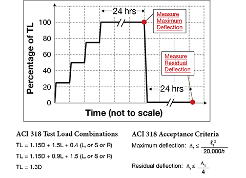
[3]The test load magnitude (TLM), including the dead load already in place, is set equal to a defined weighted combination of the design loads (Figure 2). The test load is to be applied in at least four approximately equal increments, and the structure should be adequately instrumented to capture the maximum response values. An initial set of deflection measurements of each instrument shall be recorded not more than one hour before the application of the first load increment. After the removal of the test load, a final set of deflection measurements must be taken an additional 24 hours after the test load is removed.
The structural response can be considered satisfactorily when there are no signs of failure (i.e. spalling or crushing of compressed concrete and evidence of excessive deflections), when the measured maximum deflection (Ämax) does not exceed a pre-defined threshold that depends on span and overall depth of the test member, and when residual deflections (Är,max) do not exceed 25 percent of Ämax attained during the test. If the measured maximum and residual deflections do not satisfy the acceptance criteria, the load test can be repeated at least 72 hours after the removal of the first test load.
These criteria are aimed at identifying a structure (or part thereof) that does not behave linear-elastically when tested, and the maximum allowable deflections are based on the calculation of deflections of a simply supported concrete beam when subjected to allowable-stress-design load levels. While first introduced in the early versions of ACI (Figure 1), this criterion has ‘survived’ through the years and is still part of current documents. However, newer protocols and acceptance criteria have been developed, as discussed below.
ACI 437-12
The new ACI 562-14, Code Requirements for Evaluation, Repair, and Rehabilitation of Concrete Buildings, references the new ACI 437-12, Code Requirements for Load Testing of Existing Concrete Structures and Commentary, which contains provisions for the 24-hour load test procedure, as well as a new cyclic load test. The latter option introduces hydraulics as the means for the load application and removal.
Safety advantages are obvious in comparison with more traditional methods (e.g. sandbags and steel plates) because the load can be quickly removed once the tested structure exhibits the first signs of failure. Additionally, hydraulics provides more control on the load application, enabling the reduction of the duration (and cost) of the 24-hour load test, as well as the definition of more precise load cycles. The new method for the application of the load also allowed for the definition of new acceptance criteria designed to capture non-elastic behavior of the tested structure.
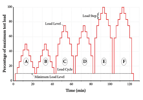
The cyclic load test protocol consists of applying concentrated loads in a quasi-static manner and in at least six cycles, with each individual cycle including four to six load steps to reach the TLM. The six cycles (A through F) are loading/unloading (Figure 3). The load applied in Cycles A and B is 50 percent of the TLM, while 75 percent of the TLM is applied in Cycles C and D, and 100 percent of the TLM is applied in Cycles E and F.
 [4]
[4]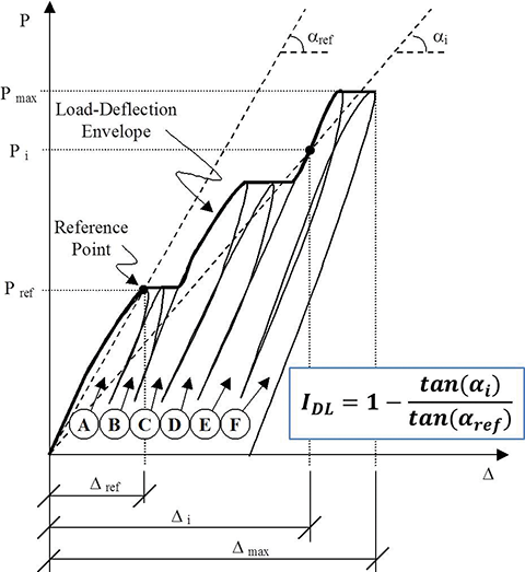 [5]
[5]ACI 437 defines three acceptance criteria and their relative limits:
- The deviation from linearity index (IDL) criterion represents the measure of the nonlinear behavior of a member being tested at any time during the test. It is defined in Figure 4, and its limit is set at 25 percent.
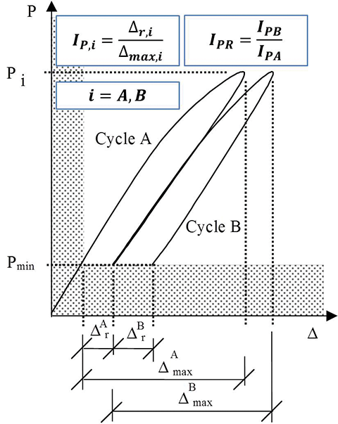
- The permanency index (IPR) criterion measures the ratio between the amounts of permanent change displayed by any structural response parameter during the first and the second of two identical load cycles (i.e. Cycles A and B, C and D, and/or E and F). It is defined in Figure 5, and its limit is set at 50 percent.
- The residual deflection criterion is the ratio between the residual deflection measured at least 24 hours after the removal of the load and the maximum deflection measured during the test. This ratio cannot be larger than 25 percent.
 [6]
[6]If one of the three acceptance criteria is not satisfied, ACI 437 allows repeating the test under the condition the maximum deflection measured during the test does not exceed 1/180 of the distance between the centers of the supports. The repeat test can be considered acceptable when the residual deflection recovery (measured at least 24 hours after the removal of the load) relative to the repeat test only is smaller than one-tenth of the maximum deflection measured during the repeat test only. Additionally, studies are currently under way to combine these parameters into one.
AISC manual
Appendix 5 of the AISC Steel Construction Manual (14th edition) provides guidance for evaluating existing steel structures (with focus on floors or roofs) by load testing for “verification of a specific set of design loadings,” or “determination of the available strength of a force resisting member of system.”
According to the manual, the test load magnitude can be calibrated to assess the structure’s strength or serviceability requirements. Also, when the strength requirements are investigated, the test load should equal the ultimate factored design load. The load should be applied incrementally, the test load held for at least one hour, and the structural response monitored at critical locations during the entire duration of the test.
The structure (or part being tested) is deemed to pass when the recorded deformations do not increase by more than 10 percent during the one-hour holding period of the test load. This document does not provide guidance on the allowable limits of permanent deformations. When the serviceability requirements are investigated, the test load magnitude should equal the service design loads, but no acceptable limits for the deformations under service conditions are provided.
Other codes
For buildings made of materials other than concrete and steel, development of the load test protocols and of the acceptance criteria is often left to the licensed design professional. For example, while mandating the load test procedure should simulate applicable loading and deformation conditions, the test load be applied for at least 24 hours, and the tested system be continuously monitored during the load test execution, IBC does not provide explicit guidance regarding the magnitude of the test load to be applied. On the other hand, some local building codes are more specific. New York City’s building code, for example, requires the test load be equal to two times the unfactored design loads.
To evaluate the response of the tested system, IBC provides two different sets of acceptance criteria. One set aims at verifying the tested system shows no evidence of failure during and after the test—in other words, excessive deflections or localized deformations obviously incompatible with safety requirements. The other set of acceptance criteria aims at verifying the measured maximum and residual deflections do not exceed the code-prescribed serviceable deflection limits and residual deformation, respectively.
Test load determination
Regardless of the selected protocol, load-testing challenges typically revolve around the tester’s ability to achieve controlled loading conditions that mimic the intended design load based on the in-service use. Matching the design loading configuration (e.g. uniform loads) during load test is often impractical or unfeasible, and engineers strive to design a less-invasive test-load pattern (e.g. patch loads) that produces equivalent effects (e.g. forces and stresses) on the tested structure.
Generally, the magnitude of the patch load can be expressed as a function of the magnitude of a uniform load through use of empirically developed coefficients, known as c1 and c2. They depend on the position selected for the patch load and account for the fact the extent of the patch load is a fraction of the extent of the distributed load—both along and perpendicular to the span of the tested structure.
In particular, the coefficients depend on the degree of fixity of the structure restraints at the span-end locations, and on the transversal stiffness of the tested member. The coefficients also account for the fact non-loaded portions of the structure ‘share’ the test load with the loaded portion.
The evaluation of these coefficients can be achieved by means of analytical and/or experimental methods. The former option mostly relies on structural and finite element (FE) analyses. For example, the global span-end stiffness due to contribution of all the members adjoining to a column can be estimated through well-known methods documented in the literature, or it can be estimated through an FE model.
 [7]
[7]Analytical methods are typically most effective in the estimation of the magnitude of the test load when the structure is well-understood and the tester has enough information to build a realistic model. This would potentially include:
- span configuration and dimensions;
- geometry of the tested section (e.g. beam, slab, etc.);
- material properties; and
- the configuration of the structure that surrounds the tested area.
However, case-specific conditions may not be conducive to allow reliance on FE or other analyses. For example, existing structural drawings may not be available, portions of the structure may be concealed or not accessible for up-close measurements, the existing material properties may be unknown, or testing could be difficult to achieve due to various reasons. In these situations, experimental methods are typically the best option, since they are based on the measurement of the deflected shape of the tested structure.
 [8]
[8]While still requiring a preliminary structural investigation (which includes a rough evaluation of the geometry and material properties), experimental methods are not affected by the lack of precise information on the tested structure. These methods also require a ‘calibration test’ (performed prior to the actual load test) to estimate the coefficients.
Both analytical and experimental approaches are valid methods, each with its own benefits and detriments—a good engineer should recognize the most appropriate method for a given situation.
 [9]
[9]Selection of load test approach and methodology
Ultimately, the design professional is responsible for the selection, design, and implementation of the load test procedure. This may include choosing the:
- load test protocol (e.g. 24-hour versus cyclic test);
- method of application of the load (e.g. water tanks versus steel plates);
- definition of the test load magnitude;
- acceptance criteria; and
- instrumentation to monitor the structural response.
All these selections depend on one another and can be optimized to reduce cost for a given structure with given restrictions.
Safety needs to be a primary concern during design and implementation of the load test. Installation of shoring, as a safety blanket, is paramount. Shoring should be configured so it does not interfere with the tests protocol and does not influence the results (by leaving a gap underneath the tested structure), and, at the same time, to provide sufficient protection in case the tested structure fails.
The method for the load application is also one of the key considerations, especially when the understanding of the existing construction, or ability to predict its behavior, is not great. Historical loading methods, like sand bags, steel plates, and bricks, require intensive labor and do not allow for quick removal of the load in case something goes wrong. They are still suitable for structures where ductile behavior and ample ‘warning’ (e.g. excessive deflections, creaking sounds) are expected prior to failure (e.g. wood joist floor systems).
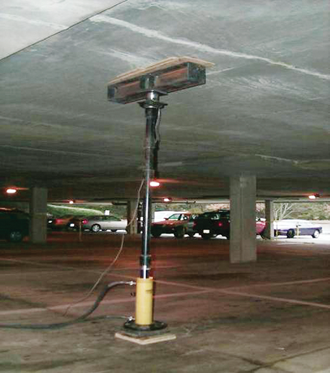
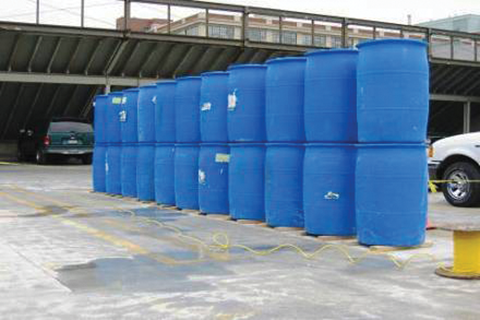
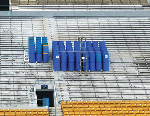
However, for structures or test configurations for which non-ductile behavior is expected (e.g. masonry arches or concrete structures tested in shear), hydraulics and water containers or tanks may be a better method for the load application because they enable quick removal. The authors used the hydraulic-cylinder load approach for load testing of several garage structures (Figure 6), and water containers to test the precast-plank-roof system of a parking garage in Boston’s Charlestown neighborhood (Figure 7), as well as the bleachers of the aforementioned university stadium (Figure 8).
 [10]
[10]Similarly, the approach for duration of test load, as well as the extent and type of data acquisition system can be tailored to meet the needs of the project at hand. Due to time and access constraints, the ‘rapid hydraulic cylinder test’ approach was selected for a garage in Atlanta, Georgia. The test results were monitored in real time, and compared to the predicted finite-element displacement at key points of the structure. In testing the bleachers of the university stadium, the authors selected a 24-hour test, where the load was applied through 208-L (55-gal) water drums, and the structural response was monitored through an array of displacement transducers (i.e. linear variable differential transformers [LVDTs]) positioned in specific locations.
For this particular project, the authors had nearly unlimited access to the top and underside of the structure (and no schedule restraints), the opportunity to review the original structural drawings, and the ability to perform destructive and non-destructive testing to spot-check information shown on the drawings. FEM analysis was used to determine the amount and location of the water drums to induce in the tested seat rows the same internal forces (i.e. shear and moment) that would be caused by a test load distributed through the whole seating section.
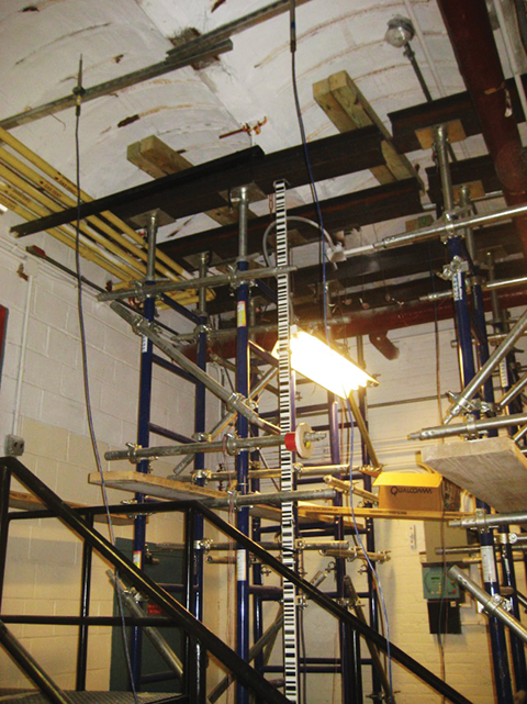
Spatial, schedule, access, and other challenges are often encountered during the planning phases of load test procedures. For example, while planning the load test of an early 1900s masonry arch floor system (Figure 9), the authors did not have access to the original drawings, and only had limited information about the construction of the arch floor system (the thickness of cinder concrete fill on top of the structural brick arch was unknown). Further, existing piping and mechanical systems hung from the underside of the test slab, obstructing installation of the instrumentation.
The lack of information on the existing structural system was addressed with a large amount of LVDTs (accompanied by strain gauges) applied to the underside of the arch and to the tie rods, by performing several FEM parametric analyses, and by running a calibration cycle prior the actual load test. Once again, since the expected deflections were a small fraction of an inch, the authors considered temperature effects in their analyses. Other early 1900s systems, where drawings are usually unavailable and where the load-test development and implementation is generally challenging, include:
- terra-cotta arches;
- wood-framed floors;
- cinder concrete slabs with draped mesh; and
- other proprietary and archaic systems.
Conclusion
Where conventional assessment or analysis methods fall short for a project, load tests can often unlock and employ the much-needed reserve strength in the examined structural systems; alternate or supplemental load paths are discovered, unaccounted-for material strength is revealed, and the hidden effects of redundancy are taken into consideration.
When properly designed and implemented, load tests are a reliable, safe, and effective tool to assess the performance of almost limitless types of structures—whether complex or simple, modern or archaic. They allow engineers to effectively employ their judgment, experience, and outside-the-box thinking to effectively and definitively assess structural behavior of the examined structure, and, in some cases, achieve much-needed peace of mind.
Filippo Masetti, PE, joined Simpson Gumpertz & Heger (SGH) in 2005, and has been involved in design, investigation, strengthening, and rehabilitation projects involving concrete, steel, masonry, fiber-reinforced-polymer, and wood structures. He is an active member of American Concrete Institute (ACI) Committee 437 (Strength Evaluation of Concrete Structures) and load-tested concrete, masonry, and wood structures. Masetti can be reached at fmasetti@sgh.com.
Antonio De Luca, PhD, joined SGH in 2013. He received his PhD from the University of Miami, with focus on the use of fiber-reinforced polymers in new construction and for the repair and rehabilitation of existing concrete structures. De Luca has worked on load-testing of existing concrete, masonry, and wood structures. He can be contacted by e-mail adeluca@sgh.com.
Milan Vatovec, PE, PhD, LEED AP, is a senior principal at SGH and the head of structural engineering at the firm’s office in New York. In his more than 16 years with SGH, he has been involved with numerous design, investigation, forensic analysis, repair and rehabilitation, and research projects. He has worked on more than 400 different projects involving evaluation and structural design for repair or modification of various existing wood, concrete, masonry, and steel structures. Vatovec is a contributing member of the Wood Committee at American Society of Civil Engineers/Structural Engineering Institute (ASCE/SEI) and of ACI Committee 440 on Fiber-reinforced Polymer Reinforcement. He can be reached at mvatovec@sgh.com.
- [Image]: http://www.constructionspecifier.com/wp-content/uploads/2015/04/bigstock-Overhead-Crane-Test-66971020.png
- [Image]: http://www.constructionspecifier.com/wp-content/uploads/2015/04/fig1-2.jpg
- [Image]: http://www.constructionspecifier.com/wp-content/uploads/2015/04/Insitu_Figure-2-.png
- [Image]: http://www.constructionspecifier.com/wp-content/uploads/2015/04/Insitu_Figure-3.png
- [Image]: http://www.constructionspecifier.com/wp-content/uploads/2015/04/Insitu_Figure-4.png
- [Image]: http://www.constructionspecifier.com/wp-content/uploads/2015/04/Insitu_Figure-5-.png
- [Image]: http://www.constructionspecifier.com/wp-content/uploads/2015/04/Insitu_Figure-6.png
- [Image]: http://www.constructionspecifier.com/wp-content/uploads/2015/04/Insitu_Figure-7.png
- [Image]: http://www.constructionspecifier.com/wp-content/uploads/2015/04/Insitu_Figure-8.png
- [Image]: http://www.constructionspecifier.com/wp-content/uploads/2015/04/Insitu_Figure-9.png
Source URL: https://www.constructionspecifier.com/weighty-matters-an-overview-of-in-situ-load-testing/