


Design examples
To illustrate the application of the relevant code requirements, this author will evaluate a typical connection—the flat bar type in Figure 8 in accordance with AISC 360.
Per AISC 360, fatigue must be considered when connections are subject to 20,000 cycles. From the information given, there are 500 vehicles entering and exiting each day over a 30-year life. Assuming the vehicles enter and exit from the same location, each joint is traversed twice per car. Cyclical loading may be calculated as follows:
500 cars x 2 axles x 2 passes = 2000 cycles/day
2000 cycles/day x 365 days = 730,000 cycles/year
730,000 cycles/year x 30 years = 21.9 million cycles
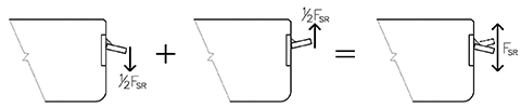
Stress within the weld subject to fatigue is limited to the Allowable Stress Range (FSR), which represents the total range of stress that may be applied to the weld—the numerical summation of tensile and compressive stresses. In a connection where the tensile stress is equal but opposite to the compression stress, half the Allowable Stress Range is available for tension and half for compression (Figure 9).
Per AISC 360, Section 2.16, the value of the Allowable Stress Range is determined by the number of cycles and the Stress Category, which is determined by comparing the connection configuration to the pictorial representations and narrative provided in Table A3.1, “Fatigue Stress Design Parameters.” Notably, a pictorial representation similar to that in Figure 10, or one approximating the severity of this example’s configuration, is not provided. It is therefore unclear such a condition was anticipated by the code. If these tables are to be used for design of precast double-tee connections, further development is warranted.
This omission notwithstanding, AISC 360’s Description 8.2 applies to “shear on the throat
of continuous or intermittent longitudinal or transverse fillet welds including fillet welds in holes or slots.” Since AISC 360 treats all stress in fillet welds as shear stress, the description of configuration 8.2 is applicable in this example. So, for this example’s purposes, the Stress Category would be “F,” and the Allowable Stress Range is 55 MPa (8 ksi). Since it has been determined half of the Allowable Stress Range is for tension and half for compression, the value of each is half of the total—27.6 MPa (4 ksi).
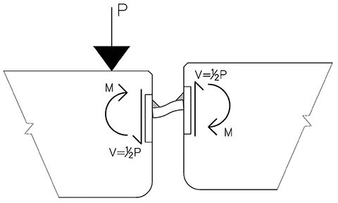
Given an Allowable Stress Range of 8 ksi, the maximum cyclical loading for which the connection is fatigue-resistant can be determined. As a load is applied to one side of a connection, half the load is transmitted across the connection to the adjacent flange (Figure 10).
As depicted in Figure 11, stress at the root of the weld during the compression cycle will greatly depend on whether the bottom of the erection bar is touching the embedded plate or not. If there is no gap, or root opening, then the erection bar bears against the embedded plate and the distance between the internal compression force (C) and tension force (T) increases, reducing the internal stress.
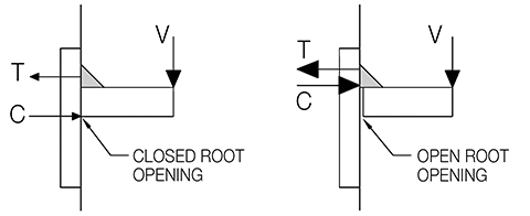
One may argue the typical root opening may be small enough it closes under load, allowing the connection to behave much like a connection with no root opening. However, under a stress of 4 ksi, the root opening need only be 0.006 mm (1/4000 in.) to never close. Given the root opening may be exceedingly small without closing under fatigue loading, any potential benefit of a closed root opening must be discounted, and the bending moment within the connection, regardless of direction, must be resisted by the weld alone.
Calculating for strength of the connection, at an Allowable Stress Range of 8 ksi, the connection can transmit 556 N (125 lb force) across the joint. As this is the load shared by each beam, it equates to a live load applied to the deck of 1112 N (250 lb) per connection.
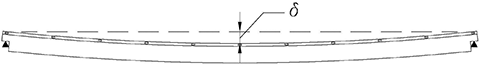
Given a maximum cyclical load of 250 lb per connection, the combined cyclical load that may be supported by the flange connections located along each edge of the beam can be calculated based on the relative deflection of the beam. From the deflected shape in Figure 12, one can see the end connections have no deflection and thus do not share the vertical load. The load is resisted by the remaining nine connections, with the largest load resisted by the center connection.


I am currently having my home remodeled and it includes a new garage. It is going to be a beautiful garage and we’ve been needing it for a long time. Since it is brand new and long awaited, I wanted to know how to maintain it well and to keep it looking it’s best. Thank you for an article it was really helpful to know how the concrete will fatigue and what to do when it does.