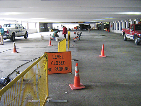
What’s wrong with my precast concrete garage?
The cyclical load supported by each connection is:
P(connection) = P(axel) x µ
Where µ is a distribution factor based on relative deflection of each connection. Calculating for the distribution factor for the center connection, where deflection is greatest, µ = 0.161 for the beam shown. The center connection, therefore, carries 16.1 percent of the cyclical load. Thus, given a maximum allowable cyclical load of 250 lb and a distribution factor of 0.161, the cyclical load P that may be supported by the beam can be calculated as:
P(connection) = P(axel) x µ
250 lb = P(axel) x 0.161
P(axel) = 1550 lb
This maximum cyclical load represents the average axle load traversing the joint and indicates that a maximum average vehicle design weight of 1406 kg (3100 lb). However, in determining whether the design is conservatively fatigue-resistant under such loading, it is important to recall some of the industry standards cited in this article do not allow connections of the configuration employed by this example, and it is not clear the configuration of this connection was considered or allowed by AISC 360. It is left to the designer, then, to determine the assumptions of this example are conservative for the specific application. This example is provided to further demonstrate the relevance of fatigue analysis in design of such connections, and to provide a basis for understanding failures observed in the field.
Discussion
Environmental Protection Agency (EPA) statistics show the average vehicle weight for the 2012 model year was 1804 kg (3977 lb), not including occupants. It is apparent, then, the connections of the double-tee beams of the example above require modification to support the fatigue loading of the average vehicle. The number of connections may be increased and the spacing decreased to meet the required loading. Alternatively, the connection details may be augmented to increase the fatigue resistance of connections.
The factors that have the greatest effect on the fatigue strength of the connection include weld size and effective joint width. However, there are tradeoffs that must be considered when varying these parameters.
The bending and fatigue resistance of the weld may be augmented by increasing the weld size. However, additional welding creates additional heat, and this has been well-established to be detrimental to the concrete in which the connections are embedded.
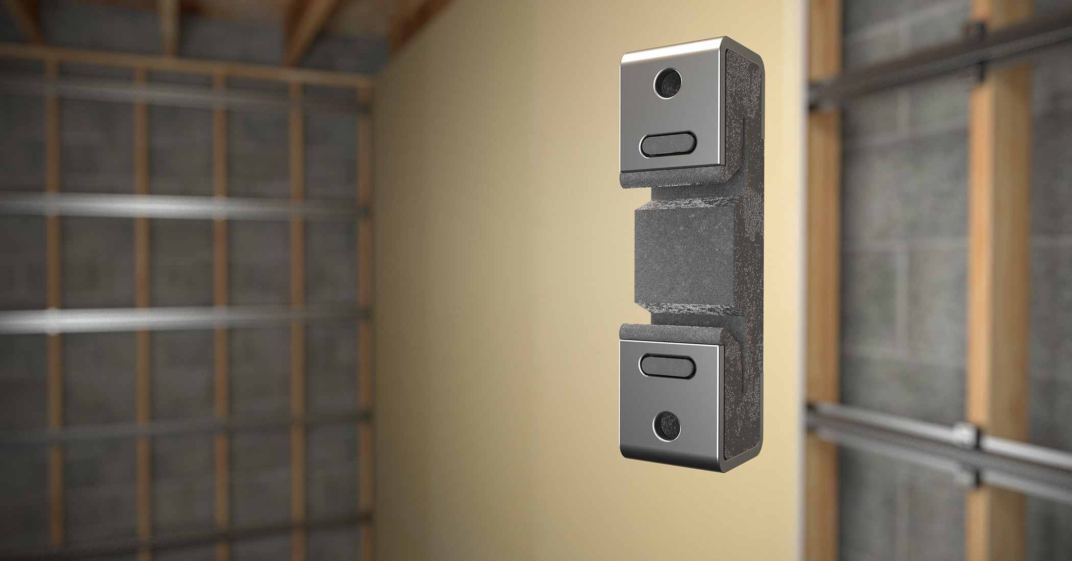
Stainless steel has a high coefficient of thermal expansion, expanding 50 percent more than mild steel when exposed to heat. As welds are performed, the portion of the stainless steel connection embedded within the concrete expands, creating cracks and spalls. These cracks allow moisture intrusion to the portions of the connection embedded within the concrete, corroding non-stainless components and causing leaks at the precast joints. It is, therefore, advantageous to limit welding heat as much as possible during erection. This may be achieved by minimizing weld size or length, or by performing multiple, smaller passes during welding.
Joint width may likewise be varied within limits. A smaller joint width between embedded plates imparts less moment on the connection. However, there are practical considerations. The smaller the joint, the more difficult it is to obtain the proper angle with a welding rod to correctly perform a fillet weld. As the joint width becomes smaller, the welding rod must be held at a steeper angle, which makes it difficult to deposit weld metal on the vertical leg of the fillet. It also becomes difficult to inspect by both the welder and the weld inspector.
There are cost implications that must also be considered in performing these welded connections. Modifying weld size on a connection that is often counted in the thousands on a project cannot be performed without significantly affecting cost. When considering such costs, it is very important to seek balance between opposing factors.
Larger welds are more costly but may improve fatigue resistance and increase the life of the structure. However, if too large, these same welds may crack the concrete and cause leaking joints and deterioration of connections. Smaller welds may be sympathetic to the concrete, but could increase propensity for fatigue failure or require additional connections be employed. For flat-bar connections, smaller joint widths increase fatigue resistance, but can make connections difficult to weld correctly and double-tee beams difficult to fabricate within tolerance.
Precast double-tee connections are subject to cyclical fatigue loading. Design of fatigue-resilient connections must consider the fatigue cycle and configuration of the connection, while remaining sympathetic to the concrete surrounding the embedments onto which they are welded.
Lawrence E. Keenan, PE, is vice president and director of engineering at Hoffmann Architects, an architecture/engineering firm specializing in the rehabilitation of the building envelope, with offices in Connecticut, New York, and Washington, D.C. He has 24 years of experience in the industry, 18 of which are with Hoffmann, where he develops remedial solutions for precast concrete structures and provides structural consultation services. Keenan can be reached by e-mail at l.keenan@hoffarch.com.
Sign up for our weekly newsletter
Architectural materials and methods delivered right to your inbox
- CSI News and Notes: CSI Foundation’s construction camp; CSI spring exam; and more
- CSI News and Notes: CSI’s credentials; CSI conference theme; and more
- To be specific – CSI supports young AECO professionals
- CSI News and Notes: CSI’s foundation scholarships, national conference, and Crosswalk
- CSI News and Notes: AI’s impact; CSI 2024 conference, and more
Products


Read the Latest Issue