What’s wrong with my precast concrete garage?
by Katie Daniel | June 1, 2015 11:39 am
 [1]
[1]by Lawrence E. Keenan, PE, AIA
Precast double-tee construction has become a dominant method for building parking garages in North America. The double-tee beam deck system of this construction type provides a finished wearing surface, supports vehicle loading, and forms an integral part of the lateral force-resisting system. However, maintenance and repair of deck connections is a common problem with this type of construction. The most common cause is perhaps the least considered.
Connections between double-tee beams are subject to a varied array of loads from seismic events and from the deck’s temperature-induced expansion and contraction. Loading from vehicles is often regarded as small and insignificant in comparison with seismic loading—unfortunately, the effects of this cyclic deflection are not often addressed in typical precast concrete garage construction. However, over time, vehicular loading can cause widespread failure of these connections and, as such, the building codes require it be considered in design.
 [2]
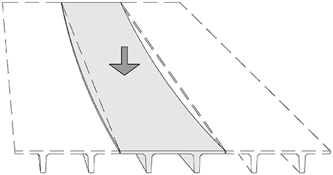
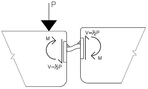
[2]The rhythmic thumping of tires while driving through a precast parking garage is a familiar experience of modern life. As the wheel traverses each beam, load is applied, and the double-tee beam deflects downward (Figure 1).
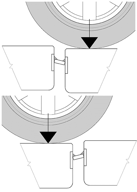
The adjacent beams resist this deflection through individual connections located along the joint between the beam flanges. Each connection shares a portion of the load proportional to the deflected shape of the beam.
As connections close to the beam’s center resist a greater amount of deflection, they transfer more load. As the vehicle traverses across the joint, loading of the connections is abruptly reversed (Figure 2).
 [3]
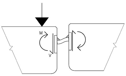
[3]As load is applied to the connection, relative deflection of adjacent concrete flanges is resisted by a field-installed erection bar. This erection bar is fixed on either side by welds, and bending moment is applied to the welds about an axis parallel to the joint (Figure 3). This moment creates a concentration of tensile stress at the root of the weld, followed immediately by compression stress as the wheel traverses the joint. With enough cycles, this stress reversal leads to fatigue failure of the weld (Figure 4).
Fatigue
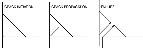
Fatigue is the process by which a material becomes weakened through cyclic loading. Over time, repeated loading leads to the development and propagation of cracks, and the eventual failure of the weld. At the microscopic level, fatigue failure occurs in three steps.
1. Crack initiation
The configuration of connections creates a severe notch at the root of the weld that is the precipitating point for crack initiation. Surface discontinuities typically cause a localized increase in stress and a nucleation point for cracks. In a welded connection, the root of the weld provides a highly irregular crevice that precipitates crack formation. In fact, many industry standards and model codes prohibit the root of the weld from being subject to tension for this very reason.
2. Crack propagation
The crack grows at this stage in a slow, stable manner—the rate of which depends on the magnitude of the stress cycle. As microscopic cracks grow into macroscopic cracks, the intact area of the weld is reduced, increasing stress on the remaining cross-section and accelerating the rate of propagation.
 [4]
[4]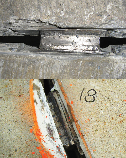 [5]
[5]
 [6]
[6]3. Failure
When the strength of the remaining intact cross-section is insufficient to withstand the applied load, failure occurs. It is typically abrupt—the weld severs completely, all at once, along a thin line at the outer face of the weld (Figure 5).
While it may seem as though such acute failure would require sustained and intense loading, it is a characteristic of fatigue that crack initiation and propagation need not occur at high stress. The main factors leading to fatigue failure are:
- number of cycles;
- severity of stress concentration created by surface defects and geometry of the detail; and
- stress range, or magnitude of the fluctuation in stress that occurs in each cycle.
In the case of stress reversal, this is the sum of the repeated tensile and compressive stresses.
Fatigue fractures are easily distinguished from other failures by their appearance. The failure surface typically has two distinct regions created during the crack propagation and failure stages. The crack propagation stage is characterized by a smooth, burnished appearance—the result of rubbing between crack surfaces during stress reversal.
 [7]
[7]This burnished surface is accompanied by numerous linear marks (‘beach marks’) arranged in parallel; each of these striations represents an individual cycle of loading and chronicles a step in the crack-formation process. Additionally, fatigue fractures of double-tee connections typically exhibit a straight, uniform crack in the propagation zone, along with a thin fracture area at the weld face (Figure 5).
Figure 6 shows a flat bar-type flange connection that failed due to fatigue. In this photo (noting the erection bar is shown upside down), there is a straight and uniform crack-propagation zone, beach marks on the failed weld surface, and an abrupt fracture at the face.
Close review of the fracture surface reveals a burnished appearance with distinguishable beach marks. As these beach marks occur at the microscopic level, they become even more apparent at higher magnifications. Figure 7 shows scanning electron micrographs of the fracture surface of two typical connections. At the microscopic level, numerous parallel striations are clearly visible—each represents the point to which the metal fractured before stress reversal.
 [8]
[8]Code requirements
It is important to note while this connection is ubiquitous in the precast industry, review of model codes and industry standards finds a general caution against using this configuration when subject to fatigue loading. Specifically, American Institute of Steel Construction (AISC) Steel Design Guide 27, Structural Stainless Steel, cautions stress concentrations, eccentricities, and fillet welds should be avoided to eliminate fatigue problems.
Moreover, connections of this nature are outright prohibited by some authorities. Both American Welding Society (AWS) D1.6, Structural Welding Code–Stainless Steel, and the U.K. Steel Construction Institute’s Design Manual for Structural Stainless Steel state fillet welds should not be used in situations that produce bending moment about the longitudinal axis of the weld when such bending causes tension at the root of the weld. These guidelines underscore the importance of fatigue considerations in the design of precast double-tee connections, and provide an explanation for many of the failures observed in practice.
The International Building Code (IBC) largely defers to the American Institute of Steel Construction (AISC) 360, Specifications for Structural Steel Buildings, for design of welded connections. However, as precast connections are typically constructed of stainless steel, AISC 360, which pertains only to structural steel, does not directly apply. Nonetheless, AISC Steel Design Guide 27 states AISC 360 may be used as long as reduced resistance factors or increased factor of safety are considered.
 [9]
[9]Design examples
To illustrate the application of the relevant code requirements, this author will evaluate a typical connection—the flat bar type in Figure 8 in accordance with AISC 360.
Per AISC 360, fatigue must be considered when connections are subject to 20,000 cycles. From the information given, there are 500 vehicles entering and exiting each day over a 30-year life. Assuming the vehicles enter and exit from the same location, each joint is traversed twice per car. Cyclical loading may be calculated as follows:
500 cars x 2 axles x 2 passes = 2000 cycles/day
2000 cycles/day x 365 days = 730,000 cycles/year
730,000 cycles/year x 30 years = 21.9 million cycles
 [10]
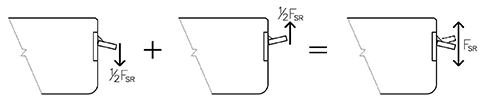
[10]Stress within the weld subject to fatigue is limited to the Allowable Stress Range (FSR), which represents the total range of stress that may be applied to the weld—the numerical summation of tensile and compressive stresses. In a connection where the tensile stress is equal but opposite to the compression stress, half the Allowable Stress Range is available for tension and half for compression (Figure 9).
Per AISC 360, Section 2.16, the value of the Allowable Stress Range is determined by the number of cycles and the Stress Category, which is determined by comparing the connection configuration to the pictorial representations and narrative provided in Table A3.1, “Fatigue Stress Design Parameters.” Notably, a pictorial representation similar to that in Figure 10, or one approximating the severity of this example’s configuration, is not provided. It is therefore unclear such a condition was anticipated by the code. If these tables are to be used for design of precast double-tee connections, further development is warranted.
This omission notwithstanding, AISC 360’s Description 8.2 applies to “shear on the throat
of continuous or intermittent longitudinal or transverse fillet welds including fillet welds in holes or slots.” Since AISC 360 treats all stress in fillet welds as shear stress, the description of configuration 8.2 is applicable in this example. So, for this example’s purposes, the Stress Category would be “F,” and the Allowable Stress Range is 55 MPa (8 ksi). Since it has been determined half of the Allowable Stress Range is for tension and half for compression, the value of each is half of the total—27.6 MPa (4 ksi).
 [11]
[11]Given an Allowable Stress Range of 8 ksi, the maximum cyclical loading for which the connection is fatigue-resistant can be determined. As a load is applied to one side of a connection, half the load is transmitted across the connection to the adjacent flange (Figure 10).
As depicted in Figure 11, stress at the root of the weld during the compression cycle will greatly depend on whether the bottom of the erection bar is touching the embedded plate or not. If there is no gap, or root opening, then the erection bar bears against the embedded plate and the distance between the internal compression force (C) and tension force (T) increases, reducing the internal stress.
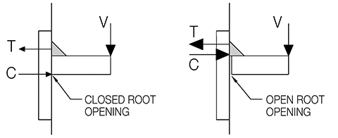 [12]
[12]One may argue the typical root opening may be small enough it closes under load, allowing the connection to behave much like a connection with no root opening. However, under a stress of 4 ksi, the root opening need only be 0.006 mm (1/4000 in.) to never close. Given the root opening may be exceedingly small without closing under fatigue loading, any potential benefit of a closed root opening must be discounted, and the bending moment within the connection, regardless of direction, must be resisted by the weld alone.
 [13]
[13]Calculating for strength of the connection, at an Allowable Stress Range of 8 ksi, the connection can transmit 556 N (125 lb force) across the joint. As this is the load shared by each beam, it equates to a live load applied to the deck of 1112 N (250 lb) per connection.
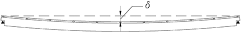
Given a maximum cyclical load of 250 lb per connection, the combined cyclical load that may be supported by the flange connections located along each edge of the beam can be calculated based on the relative deflection of the beam. From the deflected shape in Figure 12, one can see the end connections have no deflection and thus do not share the vertical load. The load is resisted by the remaining nine connections, with the largest load resisted by the center connection.
 [14]
[14]The cyclical load supported by each connection is:
P(connection) = P(axel) x µ
Where µ is a distribution factor based on relative deflection of each connection. Calculating for the distribution factor for the center connection, where deflection is greatest, µ = 0.161 for the beam shown. The center connection, therefore, carries 16.1 percent of the cyclical load. Thus, given a maximum allowable cyclical load of 250 lb and a distribution factor of 0.161, the cyclical load P that may be supported by the beam can be calculated as:
P(connection) = P(axel) x µ
250 lb = P(axel) x 0.161
P(axel) = 1550 lb
This maximum cyclical load represents the average axle load traversing the joint and indicates that a maximum average vehicle design weight of 1406 kg (3100 lb). However, in determining whether the design is conservatively fatigue-resistant under such loading, it is important to recall some of the industry standards cited in this article do not allow connections of the configuration employed by this example, and it is not clear the configuration of this connection was considered or allowed by AISC 360. It is left to the designer, then, to determine the assumptions of this example are conservative for the specific application. This example is provided to further demonstrate the relevance of fatigue analysis in design of such connections, and to provide a basis for understanding failures observed in the field.
Discussion
Environmental Protection Agency[15] (EPA) statistics show the average vehicle weight for the 2012 model year was 1804 kg (3977 lb), not including occupants. It is apparent, then, the connections of the double-tee beams of the example above require modification to support the fatigue loading of the average vehicle. The number of connections may be increased and the spacing decreased to meet the required loading. Alternatively, the connection details may be augmented to increase the fatigue resistance of connections.
The factors that have the greatest effect on the fatigue strength of the connection include weld size and effective joint width. However, there are tradeoffs that must be considered when varying these parameters.
The bending and fatigue resistance of the weld may be augmented by increasing the weld size. However, additional welding creates additional heat, and this has been well-established to be detrimental to the concrete in which the connections are embedded.
Stainless steel has a high coefficient of thermal expansion, expanding 50 percent more than mild steel when exposed to heat. As welds are performed, the portion of the stainless steel connection embedded within the concrete expands, creating cracks and spalls. These cracks allow moisture intrusion to the portions of the connection embedded within the concrete, corroding non-stainless components and causing leaks at the precast joints. It is, therefore, advantageous to limit welding heat as much as possible during erection. This may be achieved by minimizing weld size or length, or by performing multiple, smaller passes during welding.
Joint width may likewise be varied within limits. A smaller joint width between embedded plates imparts less moment on the connection. However, there are practical considerations. The smaller the joint, the more difficult it is to obtain the proper angle with a welding rod to correctly perform a fillet weld. As the joint width becomes smaller, the welding rod must be held at a steeper angle, which makes it difficult to deposit weld metal on the vertical leg of the fillet. It also becomes difficult to inspect by both the welder and the weld inspector.
There are cost implications that must also be considered in performing these welded connections. Modifying weld size on a connection that is often counted in the thousands on a project cannot be performed without significantly affecting cost. When considering such costs, it is very important to seek balance between opposing factors.
Larger welds are more costly but may improve fatigue resistance and increase the life of the structure. However, if too large, these same welds may crack the concrete and cause leaking joints and deterioration of connections. Smaller welds may be sympathetic to the concrete, but could increase propensity for fatigue failure or require additional connections be employed. For flat-bar connections, smaller joint widths increase fatigue resistance, but can make connections difficult to weld correctly and double-tee beams difficult to fabricate within tolerance.
Precast double-tee connections are subject to cyclical fatigue loading. Design of fatigue-resilient connections must consider the fatigue cycle and configuration of the connection, while remaining sympathetic to the concrete surrounding the embedments onto which they are welded.
Lawrence E. Keenan, PE, is vice president and director of engineering at Hoffmann Architects, an architecture/engineering firm specializing in the rehabilitation of the building envelope, with offices in Connecticut, New York, and Washington, D.C. He has 24 years of experience in the industry, 18 of which are with Hoffmann, where he develops remedial solutions for precast concrete structures and provides structural consultation services. Keenan can be reached by e-mail at l.keenan@hoffarch.com[16].
- [Image]: http://www.constructionspecifier.com/wp-content/uploads/2015/06/parking_IMG_4664.png
- [Image]: http://www.constructionspecifier.com/wp-content/uploads/2015/06/parking_Figure-1.png
- [Image]: http://www.constructionspecifier.com/wp-content/uploads/2015/06/Figure-2-edit.jpg
- [Image]: http://www.constructionspecifier.com/wp-content/uploads/2015/06/parking_Figure-3.png
- [Image]: http://www.constructionspecifier.com/wp-content/uploads/2015/06/Figure-4-edit.jpg
- [Image]: http://www.constructionspecifier.com/wp-content/uploads/2015/06/parking_Figure-6-ALTERNATE.png
- [Image]: http://www.constructionspecifier.com/wp-content/uploads/2015/06/parking_Figure-7-with-out-arrows.png
- [Image]: http://www.constructionspecifier.com/wp-content/uploads/2015/06/Figure-7-edit.jpg
- [Image]: http://www.constructionspecifier.com/wp-content/uploads/2015/06/parking_Figure-10.png
- [Image]: http://www.constructionspecifier.com/wp-content/uploads/2015/06/parking_Figure-11.png
- [Image]: http://www.constructionspecifier.com/wp-content/uploads/2015/06/parking_Figure-12.png
- [Image]: http://www.constructionspecifier.com/wp-content/uploads/2015/06/parking_Figure-13.png
- [Image]: http://www.constructionspecifier.com/wp-content/uploads/2015/06/parking_Figure-14.png
- [Image]: http://www.constructionspecifier.com/wp-content/uploads/2015/06/parking_Level-Closed-2.png
- Environmental Protection Agency: http://www.epa.gov/otaq/fetrends.htm
- l.keenan@hoffarch.com: mailto:l.keenan@hoffarch.com
Source URL: https://www.constructionspecifier.com/whats-wrong-with-my-precast-concrete-garage/