

Addressing flanking paths
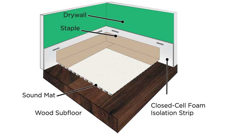
Flanking paths can be created by any rigid, sound-absorbing surface. Walls on an upper floor can transmit sound through the subfloor and into supporting walls below. When the underlayment comes into contact with a rigid surface of the structure due to poor system design or installation error, this may exacerbate the issue. This failure could be as simple as the tape between the perimeter isolation and the mat ‘lifting’ to allow the underlayment to reach the wall and the subfloor. A properly designed acoustical underlayment system provides a method to prohibit contact between the underlayment and rigid surfaces in the room. Currently, most manufacturers offer perimeter isolation in the form of a closed-cell foam strip, typically 75 to 100 mm (3 to 4 in.). This strip is applied on vertical surfaces adjacent to the substrate receiving the acoustical treatment.
While the application in Figure 5 is universally accepted as an industry standard, the actual installation of this material is often not according to the manufacturer’s specifications. These strips are commonly stapled to the walls during installation to ensure they do not release during the underlayment pour. If these mechanical fasteners are placed below the depth of the underlayment pour, they become a transmission point for vibration into the wall. Individually the effect is most likely minimal. Collectively, it can minimize the effectiveness of the system as a whole. In one lab test the authors witnessed, the test results were improved by 8 dB after correcting a flanking path on the assembly. This error occurred after careful installation in a controlled environment. This 8 dB is consistent with estimates made by V. Hongisto, a researcher from Aalto University, Finland, while developing prediction models for performance of acoustical systems in real-world applications (for more information, consult “Case Study of Flanking Transmission through Double Structures” by V. Hongisto).
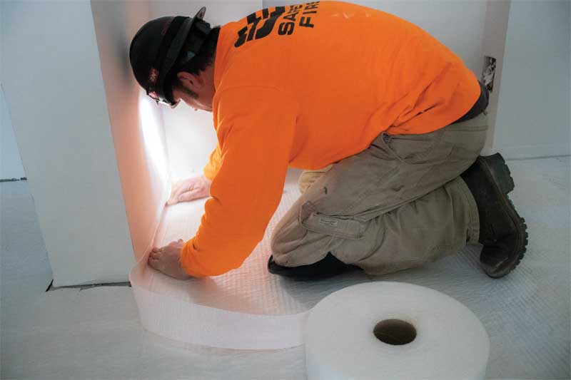
Tape is generally applied to provide a seal between the acoustical mat and the perimeter strip. Currently, the most commonly used tape is crepe, which tends to release quickly when exposed to moisture. Gypsum underlayments are poured wet, requiring the tape to maintain a strong bond to the surface of both the acoustical mat and the perimeter isolation strip to ensure underlayment does not pass through the bond and reach the subfloor or the wall. If the gypsum underlayment can create a flanking path to either of these rigid surfaces, the design professional or contractor has reduced the effectiveness of the system (Figure 6).
The rise of rigid technologies
Recently, rigid mats have become popular due to their lower-profile, thinner pour requirements, and reduced deflection. These mats rely on rigid studs closed with a membrane attached to its surface (Figure 2). Rigid innovation addresses the concerns associated with monofilament products by eliminating the deflection/compression that is tested and proven to reduce sound transmission. The advancements of rigid products have already reached deflection/compression resistance of 1580 kPa (33,000 psf) while creating only 1 mm (39 mils) of deflection.
When using a rigid mat, one is not relying on the finished floor surface to disperse the load weight over a given area. The STC and IIC results for these mats are often comparable or preferable to mass-spring vibration technology, and their compressive resistance makes them an ideal fit for modern vinyl flooring systems. The rigid support for the poured underlayment and complete decoupling from the subfloor increase the lifespan of the floor.
Field versus lab tests
The use of field tests to qualify and specify products has become popular recently for a few reasons. It is well-documented field tests are generally lower than lab due to the existence of flanking paths and a variety of real-world factors. Lab tests are designed to eliminate the flanking paths to the highest degree possible. Additionally, items such as air vents, light fixtures, truss spans, and the quality of the ceiling installation all play a role in reducing the ratings. For this reason, the International Building Code (IBC) requires a minimum SCT/IIC rating of 50 dB for testing performed in a lab, but reduces this rating hurdle to 45 dB for field results. The rationale for using field results is it is proof the assembly is actually capable of achieving the desired result. Specifiers should use caution when relying on field test reports to specify products. The assembly in question may have tested well on a particular project, but room volumes, light fixture types and locations, and truss span and stiff will all play a factor in the results achieved on a project. Lab tests, on the other hand, are pure because they eliminate most of these variables and are valid for comparative purposes.
The details really do matter. While there is no magic bullet to attain the IIC and STC ratings required for a project by local codes or clients, careful attention to the specific details pertaining to any product claims are important and worth questioning.


So considering all of this, do you recommend a specific type of underlay and or brand for a wood subfloor assembly with in floor radiant heat with LVP flooring?
There is an extra thick cork backing available that will reduce the noice to 55 using a high level LVT our HOA has been trying to find something better but there isn’t anything yet.
There is an extra thick cork backing available that will reduce the noice to 55 using a high level LVT our HOA has been trying to find something better but there isn’t anything yet.