When numbers lie: Interpreting IIC ratings for flooring underlayment performance
by sadia_badhon | October 2, 2019 12:58 pm
by Michael Martin and John Brunko
 [1]
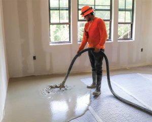
[1]Heavy steppers, clumsy residents, large pets, and excessive volume from television sets and stereos at a suite above could make life miserable in a multilevel townhome or apartment. For owners in the multifamily and the hospitality industry, these issues can also negatively impact profitability, resulting in a higher turnover or a reduction in repeat business. Although it may seem like a small part of the project, correctly understanding impact insulation class/sound transmission class (IIC/STC) ratings as well as choosing acoustical underlayments can have an immense effect on the lifetime profitability of a project and value of repeat clients and customers.
While the construction industry has seen many advancements and improvements in recent years, the numbers and accepted design practices do not always produce the expected results in real-world applications. Lab-performed tests provide a snapshot of acoustical performance. However, they do not account for the impact of load applied to the floor when a tenant moves in. At the end of the day, the acoustical performance of an assembly is determined when tenants put their heads on pillows.
A brief history of acoustical control mats
Throughout the 1950s and ’60s, new fire codes were introduced and existing ones updated to increase public safety. Gypsum was an excellent choice to increase fire-ratings for flooring assemblies due to its low-cost, lightweight, and reliable performance as a fire-rated material. Gypsum underlayments also had the added benefit of reducing sound between existing floors, and savvy marketers soon began touting these unique selling points. For customers looking for increased performance (especially under areas that would receive hard-surfaces for the finished floor), manufacturers began to produce a range of products to install before the gypsum underlayment. Sheet goods and rolled products in a variety of material types were developed as architects and owners saw the advantages of quieter units.
 [2]
[2]Typically, there have been two approaches to sound reduction: dampening (absorption) and decoupling. Absorption occurs when an underlayment ‘soaks up’ incoming acoustical energy. The material dampens the vibrations as they pass through, thus resulting in less energy output. Materials like rubber, neoprene, and foam panels do an excellent job of reducing sound in this manner.
Decoupling is accomplished by isolating surfaces entirely, resulting in two separate layers for the vibrations created by sound to pass directly through. An assembly built this way forces acoustical energy to pass through two isolated layers of noise reduction with deadening properties. Energy is lost through transference, thereby increasing the performance of the system as a whole.
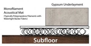
The 1980s saw the introduction of mass-spring technology mats (Figure 1). These mats proliferated in popularity due to its ease of installation, low cost, and impressive test performance. They attempt to isolate the gypsum underlayment from the subfloor entirely by using an entangled mesh of synthetic fibers, allowing the floor to float and the fibers to absorb any transferred acoustical energy from the floor above.
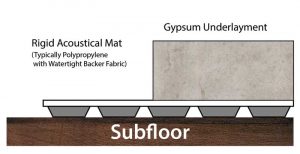
Recent years have seen the addition of a new generation of rigid mats with the ability to decouple the surfaces with a thinner profile while providing higher compressive strength (Figure 2). Required pour depths for gypsum underlayments over inexpensive monofilaments can be as thick as 38 mm (1 ½ in.) to meet the minimum requirements for sound attenuation in many regions of the United States (i.e. 50 STC and 50 IIC). Conversely, rigid mats can be 20 mm (¾ in.) deep, requiring less material for the underlayment pour while delivering ratings in the range of 60 STC and 55 IIC. When considering the added cost of materials and longer downtime on the building site to allow for proper curing of the thicker gypsum underlayment pours, these mats are competitive in terms of cost per square foot and performance when compared to monofilament technologies.
Smoke, mirrors, and STC/IIC ratings
STC is a sound rating that attempts to measure the effectiveness of an assembly in addressing ambient or airborne sound. The test measures airborne sound transmission loss between 125 and 4000 Hz IIC. Sounds defined in this range include voices, music, televisions, pet noises, and others common to habitation. When assessing STC in the lab, sounds are generated using a tone generator, and the sound pressure levels (SPLs) are measured in the testing room and the room below. The resulting loss across each of the 16 bands is evaluated and then applied to a sliding scale that essentially averages the results.
 [3]
[3]IIC is a measurement of an assembly’s ability to mitigate impacts through physical contact, such as footfalls or dropped furniture. IIC tests can be accomplished using a tapping machine that provides a series of calibrated impacts to the specified assembly. The SPL of these impacts is measured in the room with the machine and in the space below using calibrated meters. STC ratings are obtained by measuring the difference in SPL over 16 frequencies between the test room and the unit below.
Each of these tests attempts to cover a broad range of the most relevant data available for each sound class. While the tests provide useful date when considering the capabilities of a sound attenuating mat, they have some limitations. Since the human ear can detect frequencies outside of the range of these tests, they are unable to present a complete picture encompassing real-world performance.
While many people assume the resulting ratings for each of these refer to an actual drop in decibels, it is more complicated than that, and this article acknowledges its risk of oversimplifying the issues. For both STC and IIC test results, a higher rating often shows improved performance. However, since the rating is essentially an average over the 16 frequency points tested, a look at the actual test data may reveal significant deficiencies in a particular frequency range. In fact, a product can perform exceptionally well in one range, poorly in another, and still end up with a better IIC rating than a competing material that is that may have performed better in a frequency range more relevant to the project’s requirements.
 [4]
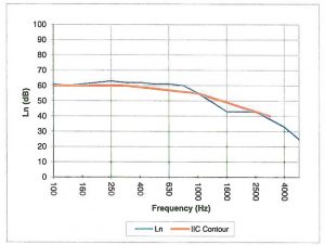
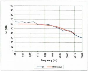
[4]The products in Figures 1 and 2 have both achieved an IIC rating of 52. While performance may seem similar at first glance, Figure 3 reveals the assembly using a rigid mat is performing consistently better at almost every frequency tested. The frequencies below 250 Hz are even more telling as these frequencies are testing almost 5 dB of pressure lower than the sound mat tested in Figure 4. This result clearly illustrates what the authors believe to be the primary shortcoming of current IIC test standards. In their paper “A dual-rating method for evaluating impact noise isolation of floor-ceiling assemblies,” John Loverde and Wayland Dong discuss the need to create an IIC testing model to address two separate frequency ranges, a solution that would allow for clearer pictures of actual test results. The authors of this article agree with this assessment as it would do much to clarify the expected performance of products for specifiers.
What is not shown in either graph, but can also significantly impact the results, are the full details of the assembly utilized to test each sound mat. Companies are quick to share the subfloor, truss assembly, channel, and gypsum board employed during testing but may not be sharing other methods used to increase the ratings. These can also include the use of non-standard insulation between the subfloor and ceiling, a high-performance pad under soft floorcoverings, or a vinyl plank floor with an attached underlayment. While these system modifications improve the performance of acoustical treatments, one now needs to specify identical products on a project in the hope of achieving the manufacturers’ published ratings.
As a best practice, all of these factors are usually considered when comparing products. It is advisable to sort through the misleading ratings by gaining access to the actual sound test data from the manufacturers showing the IIC contour line on the transmission loss graph.
The performance in relation to the IIC contour line reveals the consistency of the product over the most common frequencies as well as any deficiencies. Interestingly, standards in IIC testing change frequently, and tests performed before 1999 may not produce identical results if conducted today, so it is always a good practice to confirm the dates as well. Accurate data is derived from testing performed to ASTM E 90-09, Standard Test Method for Laboratory Measurement of Airborne Sound Transmission Loss of Building Partitions and Elements, for STC and E 492-09, Standard Test Method for Laboratory Measurement of Impact Sound Transmission Through Floor-ceiling Assemblies Using the Tapping Machine, for IIC.
When combined, these two ratings provide a snapshot of the acoustical performance of the tested assembly in a controlled environment. While these tests provide a standardized method to evaluate performance, the results alone do not tell the whole story. Understanding how to read the test data reveals the whole picture, allowing one to make an informed decision with a clearer picture of real-world performance.
The importance of transparent assemblies
 [5]
[5]It is recommended to be cautious when a manufacturer does not explicitly list each element of the assembly. As mentioned, there may be additional insulating elements in the test assembly influencing the published IIC/STC ratings. If a manufacturer offers a generalized sound data sheet, but does not list every component of the assembly, they may be hiding additional insulation or uncommonly used construction methodologies. While the lack of mechanical fasteners in the testing assembly may produce fantastic results, real-world construction practices (especially those in the multifamily and hospitality industry) include nails and screws. Performance achieved by installing the same product will most likely produce a different result. When comparing products, it is essential to compare the details of the assembly used during testing. Was the cavity filled with insulation? Are the resilient channels spaced similarly? Was an additional underlayment or membrane used on top of the gypsum? As a best practice, specifiers should always request full testing details from a manufacturer.
When reading the acoustical testing results of any product, it is beneficial to note not only the assembly used, but also the finished flooring type. Many hard-surface floors now also have an underlayment pre-attached to the planks or tiles. These pre-attached underlayments can affect the tested ratings of a floor, making an underlayment to appear as if it offers a clear advantage after installation. This advantage only exists if the same flooring is specified in the project.
Understanding the thickness and composition of the floorcovering is also critical. All ‘luxury vinyl tiles’ (LVTs) are not alike—although most projects use 2 to 3 mm (79 to 118 mils) glue-down LVT, several manufacturers still test with 5 mm (197 mils) or even thicker products because they boost performance.
Real-world performance of acoustical mats
Lab and real-world performances are, of course, two separate conditions entirely. The authors feel a few issues need to be addressed when selecting and installing sound isolation on multifamily projects. The first factor would be the effects of load on monofilament technologies over time.
 [6]
[6]Monofilament underlayments offer mechanical resistance, which is a good thing as their sound rating is dependent on the ability to maintain the ‘spring.’ If the compression on the floor increases beyond the specification, then the amount of deflection increases, thereby reducing the acoustical properties of the mat. Every mat compresses as weight increases, and this happens over time. This mechanism is known as ‘creep,’ and is common among closed-cell, low-density foams, thick fabrics, and sparsely applied monofilament mats improperly engineered to withstand loads as small as 4.8 kPa (100 psf). Creep occurs over a period of months, although it is most rapid within the first few days of a floor being loaded. As the sound mat compresses, its density and the degree of acoustical isolation are slowly compromised.
Initial compression also takes the load of the underlayment into account. The most common mats require an underlayment pour depth of 25 mm (1 in.), resulting in a load of approximately 6 kg (13 lb). While this is well below the loads measured in the manufacturer’s specifications, this assessment does not include the finished weight of loaded kitchen cabinets, heavy appliances, and furniture. However, that is not the most significant concern.
When this mass-spring vibration technology was developed and released into the market, tile was the standard choice for finished hard-floor surfaces in multifamily and hospitality sectors. By its design, rigid tile has the added benefit of dispersing any loaded weight over its surface area, thereby increasing the area of the underlayment under compression and reducing the effective load at any given point.
Recently, the market moved to LVT and luxury vinyl plank (LVP), as these materials offer significant advantages in terms of cost, ease of installation, and selection when compared to traditional hard-surface finishes like tile and wood. These materials are flexible and do nothing to disperse point loads to a broader footprint. If the specified mat has only been tested with a rigid vinyl tile or plank, the building professional and property owner may be displeased with the acoustical performance of the actual installation.
The longevity of gypsum underlayment may also become an issue as tenants move in and out of the multifamily developments. While correctly installed, cured gypsum has high compressive strength, it may compress in a localized area if the acoustical mat below it cannot properly handle the point load of a heavy object, and thereby resulting in cracking, as the material is inadequately supported. Large wood-framed buildings inevitably settle and move, even during the construction process, and cracks in the gypsum are almost always occurring to some degree. The question is, are these cracks moving beneath a compressible sound mat? The authors believe they do. The competitive nature of the construction industry has pushed pours over 10-mm (3/8-in.) thick sound mats from what used to be 38 mm 10 years ago to as little as 25 mm in recent years. It is crucial the gypsum topping is of adequate thickness when specifying compressible sound mats.
Prior to specifying, it is important to carefully review manufacturer specifications and data sheets so that all pertinent information is considered. One may be surprised to find the acoustical products used for years have made necessary changes or innovations to accommodate the same from floorcovering manufacturers.
Addressing flanking paths
 [7]
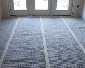
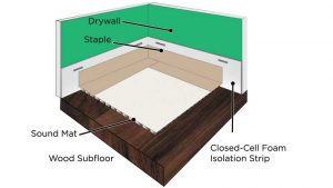
[7]Flanking paths can be created by any rigid, sound-absorbing surface. Walls on an upper floor can transmit sound through the subfloor and into supporting walls below. When the underlayment comes into contact with a rigid surface of the structure due to poor system design or installation error, this may exacerbate the issue. This failure could be as simple as the tape between the perimeter isolation and the mat ‘lifting’ to allow the underlayment to reach the wall and the subfloor. A properly designed acoustical underlayment system provides a method to prohibit contact between the underlayment and rigid surfaces in the room. Currently, most manufacturers offer perimeter isolation in the form of a closed-cell foam strip, typically 75 to 100 mm (3 to 4 in.). This strip is applied on vertical surfaces adjacent to the substrate receiving the acoustical treatment.
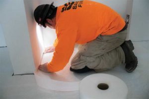
While the application in Figure 5 is universally accepted as an industry standard, the actual installation of this material is often not according to the manufacturer’s specifications. These strips are commonly stapled to the walls during installation to ensure they do not release during the underlayment pour. If these mechanical fasteners are placed below the depth of the underlayment pour, they become a transmission point for vibration into the wall. Individually the effect is most likely minimal. Collectively, it can minimize the effectiveness of the system as a whole. In one lab test the authors witnessed, the test results were improved by 8 dB after correcting a flanking path on the assembly. This error occurred after careful installation in a controlled environment. This 8 dB is consistent with estimates made by V. Hongisto, a researcher from Aalto University, Finland, while developing prediction models for performance of acoustical systems in real-world applications (for more information, consult “Case Study of Flanking Transmission through Double Structures” by V. Hongisto).
 [8]
[8]Tape is generally applied to provide a seal between the acoustical mat and the perimeter strip. Currently, the most commonly used tape is crepe, which tends to release quickly when exposed to moisture. Gypsum underlayments are poured wet, requiring the tape to maintain a strong bond to the surface of both the acoustical mat and the perimeter isolation strip to ensure underlayment does not pass through the bond and reach the subfloor or the wall. If the gypsum underlayment can create a flanking path to either of these rigid surfaces, the design professional or contractor has reduced the effectiveness of the system (Figure 6).
The rise of rigid technologies
Recently, rigid mats have become popular due to their lower-profile, thinner pour requirements, and reduced deflection. These mats rely on rigid studs closed with a membrane attached to its surface (Figure 2). Rigid innovation addresses the concerns associated with monofilament products by eliminating the deflection/compression that is tested and proven to reduce sound transmission. The advancements of rigid products have already reached deflection/compression resistance of 1580 kPa (33,000 psf) while creating only 1 mm (39 mils) of deflection.
When using a rigid mat, one is not relying on the finished floor surface to disperse the load weight over a given area. The STC and IIC results for these mats are often comparable or preferable to mass-spring vibration technology, and their compressive resistance makes them an ideal fit for modern vinyl flooring systems. The rigid support for the poured underlayment and complete decoupling from the subfloor increase the lifespan of the floor.
Field versus lab tests
The use of field tests to qualify and specify products has become popular recently for a few reasons. It is well-documented field tests are generally lower than lab due to the existence of flanking paths and a variety of real-world factors. Lab tests are designed to eliminate the flanking paths to the highest degree possible. Additionally, items such as air vents, light fixtures, truss spans, and the quality of the ceiling installation all play a role in reducing the ratings. For this reason, the International Building Code (IBC) requires a minimum SCT/IIC rating of 50 dB for testing performed in a lab, but reduces this rating hurdle to 45 dB for field results. The rationale for using field results is it is proof the assembly is actually capable of achieving the desired result. Specifiers should use caution when relying on field test reports to specify products. The assembly in question may have tested well on a particular project, but room volumes, light fixture types and locations, and truss span and stiff will all play a factor in the results achieved on a project. Lab tests, on the other hand, are pure because they eliminate most of these variables and are valid for comparative purposes.
The details really do matter. While there is no magic bullet to attain the IIC and STC ratings required for a project by local codes or clients, careful attention to the specific details pertaining to any product claims are important and worth questioning.
- [Image]: https://www.constructionspecifier.com/wp-content/uploads/2019/09/Pouring_Gypsum.jpg
- [Image]: https://www.constructionspecifier.com/wp-content/uploads/2019/09/Figure1underlay.jpg
- [Image]: https://www.constructionspecifier.com/wp-content/uploads/2019/09/Figure2underlay.jpg
- [Image]: https://www.constructionspecifier.com/wp-content/uploads/2019/09/Underlayment.jpg
- [Image]: https://www.constructionspecifier.com/wp-content/uploads/2019/09/Figure-3underlay.jpg
- [Image]: https://www.constructionspecifier.com/wp-content/uploads/2019/09/Figure-4underlay.jpg
- [Image]: https://www.constructionspecifier.com/wp-content/uploads/2019/09/Figure5underlay.jpg
- [Image]: https://www.constructionspecifier.com/wp-content/uploads/2019/09/Perimeter_Iso_Installation.jpg
- mmartin@formulatedmaterials.com: mailto:mmartin@formulatedmaterials.com
- jbrunko@formulatedmaterials.com: mailto:jbrunko@formulatedmaterials.com
Source URL: https://www.constructionspecifier.com/when-numbers-lie-interpreting-iic-ratings-for-flooring-underlayment-performance/