All photos courtesy American Wood Council
by John “Buddy” Showalter, PE, Bradford Douglas, PE, and David K. Low, PE
Many regions of the United States are at risk of high wind threats such as hurricanes, downbursts, and thunderstorms. All buildings, regardless of materials used, face risk of damage during high-wind events. The concept of resilience—the ability to withstand and recover from such events—is not new. For the built environment, techniques to improve resilience have evolved over time and continue to play an increasingly important role in creating safe, sustainable structures in which people can live and work.
When designed and constructed in accordance with modern building codes and standards, wood construction has a history of proven performance in meeting the challenges of high wind loads. One of wood’s key characteristics is it can carry substantially greater maximum loads for short durations, as is the case during high winds. For any project, a thorough understanding of the interaction between wind loads and material properties is key to the design process. A load duration factor of 1.6 is typically assumed for wind design. (Wood has several unique design characteristics, one of which is duration of load. This is the material’s ability to resist higher stresses when loads are applied for a short duration of time. In other words, wood has a higher strength when a load is applied instantaneously than it does when the load is applied for a long period. This relationship between time, strength, and load magnitude was observed as early the mid-sixteenth century. The factors used in the National Design Specification for Wood Construction [NDS] today were developed in 1948 after research conducted during World War II.)
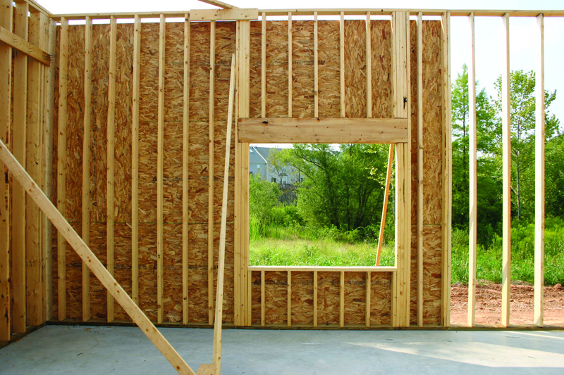
As with seismic performance, the fact wood buildings often have repetitive framing members attached with numerous fasteners and connectors also helps resist forces associated with high wind. Wood studs designed to resist wind loads in either loadbearing or non-loadbearing tall wall applications are good examples of resilient design. Tall walls can be defined as those exceeding the International Residential Code (IRC) prescriptive limits of 3.1 m (10 ft) for loadbearing walls.

Proper design of wood structures to resist such wind loads also requires correct use of wind load provisions. Minimum design loads must be in accordance with the governing building code or, where applicable, other recognized minimum design load standards such as American Society of Civil Engineers (ASCE) 7, Minimum Design Loads for Buildings and Other Structures. Wind load provisions have been developed for design of major structural elements using ‘main wind-force resisting system’ (MWFRS) loads and secondary cladding elements using ‘component and cladding’ (C&C) loads. Elements and subassemblies receiving loads both directly and as part of the MWFRS—such as wall studs—must be checked for both the MWFRS loads and C&C loads independently.
Studs should be designed using MWFRS pressures when considering the combined interactions of axial and bending stresses, and designed using C&C pressures when considering axial or bending stresses individually. This interpretation was developed because only MWFRS pressures provide loads that have been temporally and spatially averaged for different surfaces (MWFRS loads are considered to be time-dependent). Since C&C loads attempt to address a ‘worst case’ loading on a particular element during the wind event, these loads are not intended for use when considering the interaction of loads from multiple surfaces (C&C loads are not considered to be time-dependent).
This is not uncommon; in most cases, it can be considered the controlling limit in wind design of loadbearing and non-loadbearing exterior studs. However, until sufficient boundary conditions are placed on this simplification, both MWFRS and C&C load cases should be considered.


