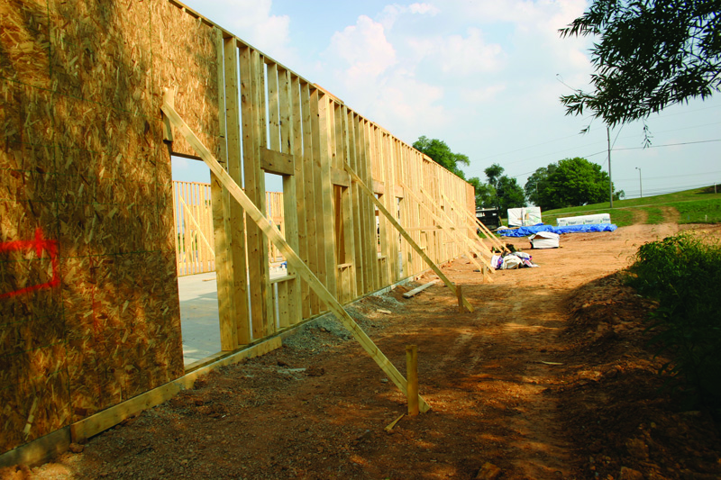
Design example
The following loadbearing stud wall design example demonstrates standard design checks for limit states of strength and deflection based on methods outlined in AWC’s 2015 NDS, SDPWS, and WFCM Workbook, along with ASCE 7-10. (This article’s example is based on a webinar, “Design of Loadbearing Tall Wood Studs for Wind and Gravity Loads [DES230],” available for free at www.awc.org. Due to space constraints, only highlights of the example are presented here, but full details can be found in the webinar materials.)
The objective is to design a 5.8-m (19-ft) tall loadbearing wall stud in a two-story building with a 6.6-m (25-ft) mean roof height, 9.8-m (32-ft) roof span, and 0.6-m (2-ft) overhangs. Wind loads are 260 km/h (160 mph) and Exposure B. Additionally, the following gravity loads are assumed for the roof:
- dead load = 0.48 kPa (10 psf);
- live load = 0.96 kPa (20 psf); and
- ground snow load = 1.44 kPa (30 psf).
These loads are assumed for the attic and ceiling:
- dead load = 0.72 kPa (15 psf); and
- attic live load = 1.44 kPa (30 psf).
The approach is to analyze wall framing as part of the MWFRS exposed to in-plane and out-of-plane load combinations specified by ASCE 7-10. Studs are then analyzed with out-of-plane C&C wind pressures only. The analysis involves an iterative approach. Initial values are selected for member properties (depth, number of members, species, and grade) and analyses completed. Then, stresses and deflections are determined and compared to allowable values. At this point, the member properties are varied, with analyses repeated until stress and deflection criteria are satisfied.
Southern pine No. 2-grade 2x8s are analyzed assuming 406 mm (16 in.) on-center (o.c.) spacing, wood structural panel exterior sheathing, and 12-mm (½-in.) gypsum wallboard interior sheathing with the following reference design values from the 2015 NDS Supplement Table 4B:
Fb = 6378 kPa (925 psi);
Fc = 9308 kPa (1350 psi);
E = 9,652,660 kPa (1,400,000 psi); and
Emin = 3,516,326 kPa (510,000 psi).
The wall stud bending strength and stiffness design value adjustment factor from SDPWS Table 3.1.1.1 for a 2×8 is equal to 1.25. Load duration factors (CD) apply to the bending and compression design values, but not modulus of elasticity. CD also varies depending on the shortest load duration in the load combination. For load combinations including:
- wind, CD = 1.6;
- roof live loads, CD = 1.25; and
- snow loads, CD = 1.15.
The following Allowable Stress Design (ASD) load combinations per ASCE 7-10 are evaluated for this example:
1. D
2. D + L
3. D + (Lr or S or R)
4. D + 0.75L + 0.75(Lr or S or R)
5. D + (0.6W or 0.7E)
6a. D + 0.75L + 0.75(0.6W) + 0.75(Lr or S or R)
6b. D + 0.75L + 0.75(0.7E) + 0.75S
7. 0.6D + 0.6W
Where:
D = dead load;
L = live load;
Lr = roof live load;
W = wind load (note the 0.6 load factor will be included in the velocity pressure calculations); and
S = snow load.
Both balanced and unbalanced snow loads are analyzed. For this example, an unbalanced snow load of 5.25 N/mm (360 plf) provides the highest snow loads on the studs.


