Wood floor assemblies easing the burden: Using technology and planning for avoiding HVAC conflicts
by Catherine Howlett | June 1, 2013 10:02 am
 [1]
[1]by Jeremy Dummer
From a single-family home to a 40-story office building, all structures are made up of a complex array of systems competing for limited space. Nowhere is this more pronounced than in floor assemblies where HVAC ducts, recessed light fixtures, and plumbing are interwoven with joists and beams.
Without carefully integrated planning of both structural and mechanical systems, conflicts can arise on the jobsite. To avoid costly and time-consuming rework, structural frame design software can help improve communication among designers and contractors.
For residential projects, the 2012 International Energy Conservation Code (IECC) offers specifiers two options when it comes to ductwork: install all ducts completely within the building’s thermal envelope or meet stringent finished system leakage requirements of less than 1.9 L/s per 9.3 m2
(4 cfm/100 sf) of conditioned floor area at 25 Pa (0.5 psf). Even in areas where the IECC has not been adopted, the majority of builders are moving ducts inside the energy envelope because it makes sense from a cost/benefit perspective.
The National Renewable Energy Laboratory (NREL), a division of the U.S. Department of Energy (DOE), notes it is relatively inexpensive to place ducts in conditioned spaces during construction and can reduce electricity demand for cooling by about 15 percent. It also reduces the required capacities for the heating and cooling systems.
 [2]
[2]NREL analysis also shows locating ducts within conditioned spaces are a more cost-effective investment than other common energy efficiency improvement measures, such as:
- R-15 or R-19 walls;
- R-40 or R-50 attics;
- low-solar heat gain coefficient (SHGC) windows; and
- seasonal energy efficiency ratio (SEER) 15 or 17 air-conditioners.
Those measures should still be taken, but placing HVAC ducts in the thermal envelope provides the greatest financial return.
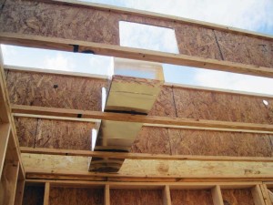
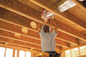
In practice, placing HVAC inside a home’s thermal envelope often means running ducts through the floor joists and cavities. The challenge is other mechanicals, such as plumbing, typically occupy the same area. Engineered wood I-joists can be cut to accommodate all the elements, but doing so properly calls for advanced planning and cooperation among trades.
 [3]
[3]Images courtesy Weyerhaeuser
Coordinating efforts
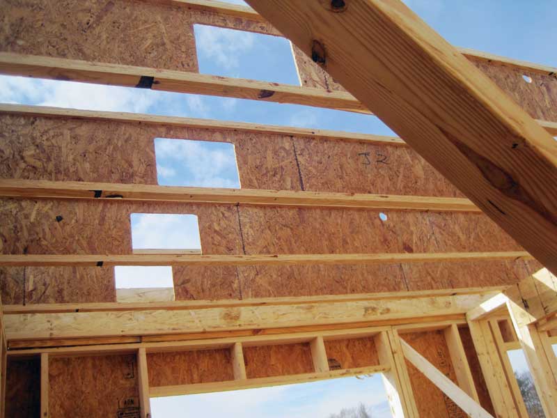
Along with their strength and consistency, I-joists are extremely adaptable to accommodate HVAC ducts, pipe runs, low-voltage wiring, and other elements requiring pathways through the floor system. Large, numerous holes can be cut into I-joist webs in the field, or prior to jobsite delivery, without effectively compromising their structural performance, provided certain guidelines for hole number, size, and placement are followed. This is in sharp contrast to solid-sawn lumber, which is much more limited in the size and number of holes it can accommodate.
Even with these capabilities, the increasing complexity of numerous elements can lead to problems if the task is not pre-planned and properly communicated among the subcontractors. Mistakes in hole-cutting—such as cutting too close to the end, too close together, or into the flange—can affect the joist’s structural performance and lead to expensive and time-consuming red flags, joist repair, or replacement. Additionally, poor planning can lead to inefficient ductwork, with longer runs and unnecessary bends, and can complicate plumbing installation.
 [4]
[4]Problems are amplified because trades rarely communicate, or change from project to project; they are infrequently brought into the planning stages. Often, the HVAC installer is hired long after the planning process is complete and has little, if any, involvement in engineering ductwork into the layout.
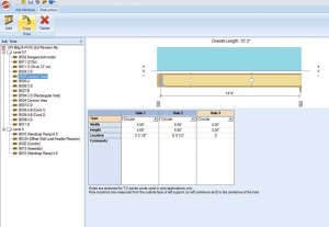
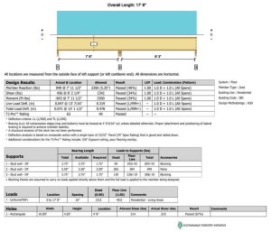
One of the best ways to manage these problems and space constraints is with advanced planning. Involving all participating trades up front allows mechanical layouts to be chosen based on the most ideal and practical locations, and the ability of the I-joists to accommodate the required holes. Structural frame design programs can help by laying out each joist and beam to scale and identifying framing conflicts with mechanical systems before construction even begins. Layouts can then be modified to accommodate non-structural requirements, such as plumbing drops, and holes in I-joists can be laid out ahead of time.
All this information can be included in a floor layout plan, giving framing crews a precise picture of what needs to be done. This greatly simplifies work for framers and mechanical installers in the field. Technology can take the concept even further as joist holes can be pre-cut to help reduce the risk of crews compromising the structure by cutting holes outside of a joist’s design parameters (e.g. holes too large or close to the joist ends).
Solutions and software
Design software at the dealer level allows the supplier to turn floor plans into step-by-step framing guides and precise framing packages. Working with the builder and subcontractors, the lumber and building material dealer designs the structure using 3-D modeling tools to determine where to route components, overlaying each mechanical element onto each other to view the entire structure as a system. From there, the dealer can provide installers with detailed instructions or use computer-controlled fabrication equipment to produce floor framing packages that install faster, safer, and with less material waste than conventional methods.
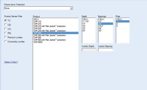
Pre-cut I-joist holes can be included in the package, eliminating the need to cut them onsite and helping to avoid potential complications. The software can also mark attachment points for intersecting framing members such as the juncture of rim board and I-joists—this ensures framing contractors do not alter the layout and potentially impede the pre-cut joist openings.
Such technology was a vital tool for a recent residence hall building at a university in Seattle. The I-joist manufacturer met with HVAC and plumbing subcontractors for the five-building project in advance, walking them through the software program and educating them on how to plan for holes in the joists.
 [5]
[5]The joists were more shallow than typical, being 241 mm (9 1⁄2 in.) deep instead of 302 mm (11 7⁄8 in.). This placed additional restrictions on the number and size of holes. However, use of the software upfront allowed for pre-planning to ensure crews knew exactly where to install lines, avoiding field calculations while helping to avoid mistakes and costly repairs or replacements.
Rethinking framing members and bringing in the whole team early on is certainly a shift in approach for many builders and installers, but it is a necessary step that has helped the builder improve future building performance.
Similarly, a Bethesda, Maryland-based residential developer used software as part of its efforts to refine its building processes. In anticipation of impending energy code changes, the developer began evaluating a range of strategies to meet new mandates. With the assistance of the Home Innovation Research Labs under the umbrella of the Department of Energy’s Building America program, this effort culminated in the construction of a test house approximately 45 percent more efficient than the requirements of 2006 IECC.
A number of measures were implemented to boost energy savings, including better air sealing and insulation, and the overall structure itself was re-evaluated. Most notable was a switch to advanced framing, including 609-mm (24-in.) on-center (oc) wall spacing that helped cut down on materials and installation time while providing increased cavity area for more robust insulation. Advanced framing also meant fewer I-joists to cut through to run HVAC.
 [6]
[6]Transitioning to a new framing system and accommodating new mechanical routes required bringing trade partners on board well in advance to plan—and to firmly establish buy-in on the vision and mission. To design the framing system, a design team and third-party engineer worked with their trade partners and a wood products manufacturer. With the aid of framing software modeling tools the layout, including the most efficient placement for ductwork, plumbing, and wiring, was designed. The entire framing system was pre-cut with a computer-aided system, labeling components with an ink-jet printer to simplify assembly onsite.
Moving ductwork out of the unconditioned attic allowed the size of its HVAC system to decrease, while lessening requirements for duct insulation. With that change, the decision to pre-cut was an easy one.
Conclusion
As demand, government regulation for more energy-efficient buildings, and market competition continue to climb, improving performance and reducing waste within the HVAC system may not be optional. Moving heating and cooling from the attic into the energy envelope is one that takes planning and foresight, but reaps the rewards of cost savings for the occupant through decreased energy loss and smaller requirements for overall HVAC capacities. Software solutions and pre-cut framing packages ease the burden by pre-planning for mechanical installation through I-joists, ensuring proper placement, installation, and long-term HVAC performance.
Jeremy Dummer is a technology advisor for Weyerhaeuser. He has worked with the company for 16 years and in his current role he consults with building material designers to maximize software technologies and successfully integrate programs into various operations. Dummer can be contacted via e-mail at jeremy.dummer@weyerhaeuser.com[7].
- [Image]: http://www.constructionspecifier.com/wp-content/uploads/2015/11/software_Winchester-holes-with-duct.jpg
- [Image]: http://www.constructionspecifier.com/wp-content/uploads/2015/11/software_Winchester-holes.jpg
- [Image]: http://www.constructionspecifier.com/wp-content/uploads/2013/06/software_Hole-Entry-Multiple-members-on-left.jpg
- [Image]: http://www.constructionspecifier.com/wp-content/uploads/2013/06/software_Can-design-holes-in-entire-TJI-product-line.jpg
- [Image]: http://www.constructionspecifier.com/wp-content/uploads/2013/06/software_Rectanglular-Hole-Example-Out-put.jpg
- [Image]: http://www.constructionspecifier.com/wp-content/uploads/2013/06/Ijoist-Installation.jpg
- jeremy.dummer@weyerhaeuser.com: mailto:jeremy.dummer@weyerhaeuser.com
Source URL: https://www.constructionspecifier.com/wood-floor-assemblies-easing-the-burden-using-technology-and-planning-for-avoiding-hvac-conflicts/